blink
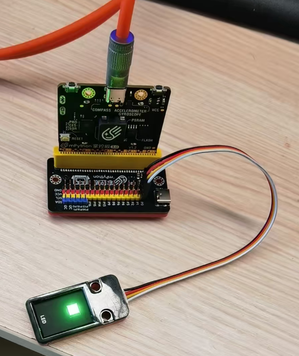
硬件连接,如下图所示,将LED模块连接到拓展板P0引脚。
选择mPython V3开发板

选择板子对应的串口

示例代码
示例-blink.ino
 1/*
 2  Blink
 3*/
 4#define PIN_LED P0
 5
 6void setup() {
 7  // initialize digital pin LED_BUILTIN as an output.
 8  pinMode(PIN_LED, OUTPUT);
 9}
10
11// the loop function runs over and over again forever
12void loop() {
13  digitalWrite(PIN_LED, HIGH);  // turn the LED on (HIGH is the voltage level)
14  delay(1000);                      // wait for a second
15  digitalWrite(PIN_LED, LOW);   // turn the LED off by making the voltage LOW
16  delay(1000);                      // wait for a second
17}
编译并上传
代码上传后,掌控板会自动运行代码,LED会闪烁。
analogRead() analogWrite()
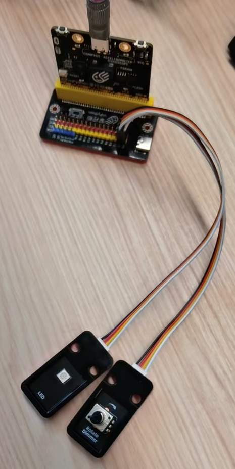
硬件连接,如下图所示,将LED模块连接到拓展板P1引脚,旋钮电位器接P0。
示例代码
示例-analog.ino
 1/*
 2  模拟输入 模拟输出 串口输出示例
 3  读旋钮电位器值,把值映射到0-255,再通过
 4  模拟输出控制LED亮度,串口打印输出值。
 5*/
 6
 7// These constants won't change. They're used to give names to the pins used:
 8const int analogInPin = P0;  // Analog input pin that the potentiometer is attached to
 9const int analogOutPin = P1;  // Analog output pin that the LED is attached to
10
11int sensorValue = 0;  // value read from the pot
12int outputValue = 0;  // value output to the PWM (analog out)
13
14void setup() {
15  // initialize serial communications at 9600 bps:
16  Serial.begin(115200);
17}
18
19void loop() {
20  // read the analog in value:
21  sensorValue = analogRead(analogInPin);
22  // map it to the range of the analog out:
23  outputValue = map(sensorValue, 0, 4095, 0, 255);
24  // change the analog out value:
25  analogWrite(analogOutPin, outputValue);
26
27  // print the results to the Serial Monitor:
28  Serial.print("sensor = ");
29  Serial.print(sensorValue);
30  Serial.print("\t output = ");
31  Serial.println(outputValue);
32
33  // wait 2 milliseconds before the next loop for the analog-to-digital
34  // converter to settle after the last reading:
35  delay(200);
36}
运行效果
代码上传后,接在P1的LED会根据P0引脚的模拟输入值调整亮度, 串口打印P0采样值及模拟输出值。